Current Location:
What Is a Starter Motor and How Does It Start an Engine?
2026-10-01Every time you turn the key or push the start button in your vehicle, a small but powerful electric motor fires up silently beneath the hood—the starter motor. It is the component that breaks an internal combustion engine's thermodynamic chicken-and-egg problem: the engine cannot run on its own until it is already running. The starter motor is the external cranking source that solves that paradox, delivering the initial mechanical impulse that allows fuel combustion to take over and sustain the cycle. This article explains exactly what a starter motor is, how the broader starting system works, and the step-by-step engine starting process from the moment you turn the ignition to the first cylinder firing.


An internal combustion engine converts the chemical energy of fuel into mechanical work through repeated combustion events inside cylinders. But before those events can occur, the crankshaft must already be rotating so that pistons can draw in an air–fuel mixture, compress it, and present it to a spark plug at precisely the right moment. This creates a circular dependency: the engine needs to be turning to run, but nothing is making it turn before the first combustion stroke.
In a four-stroke cycle, the compression stroke alone on a typical four-cylinder petrol engine requires the crankshaft to overcome several hundred psi of cylinder pressure. A healthy engine at room temperature needs to be spun to roughly 100–250 rpm before cylinder pressure drops enough for the starter to complete a full compression cycle. A cold engine, with thicker oil and higher mechanical resistance, may require even more cranking torque. Human muscle is not enough—the starter motor provides the external mechanical energy that bridges this gap.
What Is a Starter Motor?
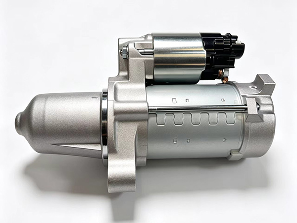
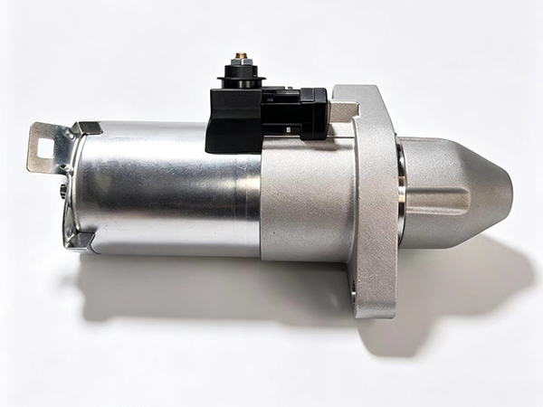
A starter motor is a high-torque, low-speed series-wound direct current (DC) electric motor purpose-built for one task: rotating an engine's crankshaft fast enough to initiate the combustion cycle. Unlike motors designed for continuous duty, a starter motor is engineered for intermittent, high-torque bursts of no more than 30 seconds at a time, because generating several horsepower for even a minute causes catastrophic overheating of its windings.
Most automotive starter motors operate on the vehicle's 12V electrical system (commercial diesel vehicles commonly use 24V). A modern 12V starter motor in good condition can draw anywhere from 60A to over 300A during a normal cranking event—peaks that would light up a welding arc. This is why battery condition is inseparable from starting system reliability: a weak battery causes voltage sag under load, reducing the magnetic field strength in the starter's field coils and producing insufficient cranking torque.
Core Components Inside a Starter Motor
Understanding the physical structure clarifies how the device achieves its role in cranking the engine:
Yoke and field coils: The stationary outer housing contains powerful permanent or electromagnetic field poles that interact with the rotating armature to produce torque.
Armature: The rotating shaft with wound copper coils, mounted on bearings. Current flowing through the armature coils creates a magnetic field that interacts with the field poles to generate rotation.
Commutator and brushes: The commutator is a segmented copper ring at the armature's end that reverses the direction of current flow through the armature coils as the armature rotates, ensuring continuous unidirectional torque. Carbon brushes press against the commutator to deliver current from the stationary battery circuit to the rotating armature.
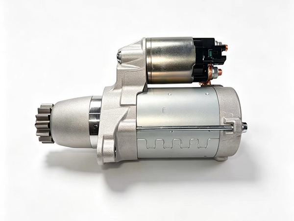
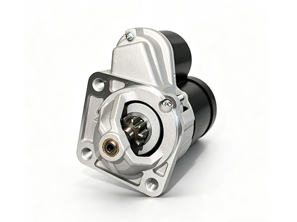
Pinion and overrunning clutch: A small gear (pinion) at the output shaft meshes with the engine's flywheel ring gear. An overrunning clutch prevents the engine from driving the starter motor backward once the engine starts running—without this clutch, the starter could spin at engine rpm and destroy itself.
Solenoid: An electromagnetic switch mounted on top of the starter body that performs two functions: it pushes the pinion gear forward to mesh with the ring gear, and it closes the heavy main contact that feeds high current from the battery to the motor windings.
The Starting System: More Than Just the Starter
The starter motor is the visible actor, but it cannot function without the rest of the starting system: the battery, wiring, ignition switch, neutral safety switch (or clutch switch on manual transmissions), relay, and solenoid. These components form the ignition switch circuit that controls when and how the starter is energised.
The battery provides the large reservoir of electrical energy. The ignition switch is the driver interface. The relay (on many vehicles) acts as a signal amplifier—a small current from the ignition switch triggers a magnetic coil that closes a heavy set of contacts, allowing the battery's full current to reach the solenoid. The solenoid does the physical heavy lifting: when energised, its plunger pushes the pinion into mesh and closes the main motor contacts simultaneously.
This layered design serves a practical purpose. The wiring from the ignition switch to the relay carries only a few amps; the wiring from the battery through the solenoid to the starter carries hundreds of amps. Keeping the high-current path short and thick prevents voltage drop in the circuit, which is critical because even a 0.5V sag under full cranking load can reduce starter torque by 15% or more.
Step-by-Step: The Engine Starting Process
1. The Driver Actuates the Ignition
When you insert the key and turn it to the Start position (or press the start button on a push-start vehicle), the ignition switch circuit closes. Current flows from the battery through the ignition switch, through the neutral safety switch (which confirms the transmission is in Park or Neutral, or the clutch pedal is depressed on a manual), and into the starter relay's coil. The relay energises and its contacts close, sending battery voltage to the solenoid's pull-in and hold-in windings.
In a push-button system, the process is similar, but the ignition switch is replaced by a body control module that validates key fob authenticity, brake pedal status, and other preconditions before activating the starter relay.
2. The Solenoid Engages and Powers the Starter
When the solenoid receives current, two things happen nearly simultaneously. First, the plunger moves forward, mechanically pushing the starter's pinion gear along a spline to mesh with the flywheel ring gear on the engine's flexplate or flywheel. Second, the plunger's movement closes a heavy set of internal contacts that complete the circuit from the battery to the starter motor's field coils and armature. At this moment the motor begins to draw full current and generate torque.
The pinion gear is intentionally smaller in diameter than the ring gear. This gear-reduction ratio—typically between 10:1 and 20:1—means the pinion must spin 10 to 20 revolutions for every single revolution of the engine's crankshaft. This multiplies the starter motor's relatively high-speed, lower-torque output into the very high torque required to overcome cylinder compression. A pinion rotating at approximately 2,000–3,000 rpm (the normal no-load speed of a 12V starter) therefore produces a crankshaft cranking speed of roughly 100–300 rpm after reduction.
3. The Engine Cranks and Early Combustion Begins
With the pinion now engaged and spinning, the starter motor is cranking the engine. The engine's crankshaft turns, driving the camshaft(s) via timing belt or chain, which opens and closes valves in the correct sequence. Air and fuel enter the cylinders (or air alone in a diesel), compression occurs, and spark plugs fire (in petrol engines).
On a cold start, cylinder wall temperatures are low, oil is viscous, and mechanical friction is at its peak. The starter must produce sufficient torque to push pistons through this resistance. A cold start demands more from the starting system than a warm start: cranking torque requirements can be 30–50% higher when engine oil is cold. This is why weak batteries and degraded starters fail disproportionately in cold weather—the electrical and mechanical demands exceed what the weakened system can supply.
A warm start faces much lower friction because oil has circulated and the engine is already near operating temperature. The same starter delivers the same mechanical power, but the engine needs less of it to reach sustained combustion.
4. The Engine Reaches Self-Sustaining Speed
The transition from starter-driven cranking to self-sustained operation is the critical handover. Once the engine reaches roughly 400–800 rpm and combustion is occurring reliably in at least one cylinder, the energy produced by the combustion events exceeds the energy needed to keep the engine turning. The starter's job is complete.
At this moment, the driver releases the key from the Start position (or lifts their finger from the start button). The ignition switch circuit opens, cutting current to the solenoid's hold-in winding. The solenoid plunger returns under spring force, pulling the pinion gear out of mesh with the ring gear and opening the main motor contacts. The starter motor disengages and coasts to a stop. The overrunning clutch ensures the engine cannot back-drive the starter during this disengagement.
The Flywheel Ring Gear: Where Torque Is Transferred
The flywheel ring gear is a toothed steel ring press-fitted or bolted to the engine's flywheel (on manual-transmission vehicles) or flexplate (on automatics). It is the interface point between the starter motor and the engine's crankshaft. The ring gear has significantly more teeth than the pinion—often between 110 and 140 teeth on a typical passenger vehicle—which achieves the high reduction ratio needed to amplify starter output torque.
Starter pinion wear, chipped ring gear teeth, and improper pinion-to-ring-gear spacing are common causes of starting system failure. When the starter pinion fails to fully disengage after cranking, the overrunning clutch prevents damage to the starter motor windings, but continued engagement causes rapid wear on both the pinion and the flywheel ring gear. A damaged ring gear produces a characteristic grinding noise when the starter is engaged, distinct from the normal whirring sound of a healthy engagement.
The Battery and Cranking Circuit: The Unseen Partner
No discussion of how a starter motor starts an engine is complete without examining the battery and cranking circuit. The battery is not merely a power source—it is a chemical reservoir that provides the massive current surge the starter demands. Under full-load cranking conditions, battery voltage can drop from 12.6V (fully charged, resting) to 9V or lower on a healthy battery, and to 6V or below on a weak battery. At 6V, most 12V starter motors produce less than a quarter of their rated torque.
The cranking circuit includes all wiring, connectors, and terminals between the battery and the starter motor, plus the ground path from the engine block back to the battery. Corroded terminals, loose ground straps, undersized wiring (common in aftermarket installs), and worn battery cables all contribute to resistance in the circuit, reducing voltage at the starter and directly reducing cranking performance. In fleet maintenance contexts, voltage drop testing of the cranking circuit is a standard diagnostic procedure: under a 100A load, the total voltage drop from battery positive terminal to starter terminal should not exceed 0.5V, and the ground circuit drop should not exceed 0.3V.
What Happens When the Starting System Fails?
Starting system failures manifest in recognisable patterns. A clicking noise when the key is turned points to insufficient battery voltage—enough to energise the solenoid's pull-in winding but not enough to close the main contacts. A slow, labored cranking noise that does not accelerate indicates a weak battery or high resistance in the cranking circuit. A starter that spins freely but the engine does not turn is a symptom of pinion-ring gear misalignment or a failed overrunning clutch that has allowed the pinion to spin independently of the gear.
Modern vehicles add complexity: stop-start systems engage and disengage the starter motor thousands of times per year, requiring components with dramatically higher durability than a conventional starter. Belt-driven integrated starter-generators (ISG) in mild hybrid architectures blur the line between starter and alternator. Nevertheless, the fundamental principle remains unchanged: the starter motor must deliver a high-torque burst of mechanical energy to overcome compression and momentum, initiating the combustion that sustains the engine thereafter.
Frequently Asked Questions
What is the difference between a starter motor and an alternator?
A starter motor converts electrical energy from the battery into mechanical torque to rotate the engine's crankshaft during start-up—it operates for only a few seconds at a time. An alternator converts mechanical energy from the engine's crankshaft into electrical energy to charge the battery and power vehicle accessories while the engine runs. They perform opposing energy conversion functions in opposite directions of the vehicle's power flow.
How much power does a starter motor draw?
A typical 12V automotive starter motor draws between 60A and 300A during cranking, depending on engine displacement, temperature, and battery condition. The power output of a starter motor is approximately 0.5kW to 2.5kW (roughly 0.7 to 3 horsepower) for a few seconds. This brief, intense power demand is why battery condition is the single most important factor in reliable engine starting.
Can a starter motor be repaired, or must it be replaced?
Both approaches exist. Individual starter motor components—brushes, commutator segments, the solenoid, and the overrunning clutch—can be replaced during a rebuild, which is standard practice for remanufactured starter motors. Complete unit replacement is common when the armature, field coils, or bearings are damaged. Remanufactured units offer a cost-effective middle ground, reusing the core casting with new internal components to original equipment specifications.
Why is cold starting harder on the starter motor?
Cold temperatures thicken engine oil, increasing mechanical friction that the starter must overcome. Cold also reduces battery capacity: a lead-acid battery at −18°C (0°F) delivers roughly 40% of its rated cranking amperage compared to room temperature. Both effects combine to demand significantly more torque from the starter motor in cold conditions while simultaneously reducing the electrical power available to generate that torque.
What role does the flywheel ring gear play in the starting system?
The flywheel ring gear serves as the toothed interface between the starter's pinion gear and the engine's crankshaft. Its larger diameter and higher tooth count relative to the pinion create the gear-reduction ratio that transforms the starter motor's high-speed, moderate-torque output into the low-speed, extremely high-torque input needed to turn the crankshaft against cylinder compression. Without this reduction ratio, no practical DC motor could crank a car engine directly.
Need a Reliable Remanufactured Starter Motor?
Cangzhou Shuomei Automotive Parts Co., Ltd. is a China-based manufacturer of remanufactured car starter motors, serving auto parts distributors, workshops, and fleet operators worldwide. Each unit is disassembled, cleaned, inspected to OE tolerances, and reassembled with new friction materials, bearings, brushes, and solenoids before dynamometer testing.
Visit the homepage to browse the current product range and request a quote: https://www.shuomei-autoparts.com
Conclusion
The starter motor is a deceptively simple device: a high-torque DC motor purpose-built to deliver a short, powerful mechanical impulse that breaks the circular dependency at the heart of the internal combustion cycle. It works in concert with the battery, the ignition switch circuit, the solenoid, and the flywheel ring gear to achieve one critical outcome—rotating the crankshaft at sufficient speed for combustion to begin and the engine to take over its own operation.
Understanding the engine starting process from first principles clarifies why cold start conditions stress the system, why battery condition is non-negotiable for reliable cranking the engine, and why the starting system is engineered as an integrated circuit rather than a single component. Whether you are diagnosing a no-crank condition, specifying replacement parts for a fleet, or evaluating a remanufactured unit for performance and durability, the concepts covered here—gear reduction, solenoid operation, overrunning clutch function, and the battery cranking circuit—form the technical foundation for every decision in this space.
References
Bosch, R. (Ed.). Bosch Automotive Handbook, 10th Edition. Robert Bosch GmbH / SAE International, 2021.
Hillier, V.A.W., & Coaker, P. Fundamentals of Motor Vehicle Technology, 7th Edition. Edinburgh: Elsevier, 2021.
Society of Automotive Engineers. SAE J541: Voltage Range for Routing Primary SAE Battery Wiring. SAE International.
IEEE. "Standard for Crankshaft Rotation Speed in Internal Combustion Engines." IEEE 568–2018.
Williamson, M.S. & Ribbens, W.B. Understanding Automotive Electronics, 8th Edition. Butterworth-Heinemann, 2017.